Introduction
The critical role of safety in modern manufacturing
Safety is the foundation of operational excellence and not just a regulatory checkbox. In today’s industrial environments, protecting personnel, equipment, and operations is essential for maintaining uptime, reducing liability, and preserving trust. A well-implemented safety system enables smoother operations by preventing incidents before they occur. When safety is treated as a fundamental part of engineering and operations, manufacturers gain stability, clarity, and resilience.
Why safety is more than just compliance
Compliance is only the beginning of a true safety strategy. Meeting standards such as ISO 13849, ANSI B11, or OSHA requirements is necessary, but it does not ensure that a facility is truly safe. True safety comes from a proactive mindset. It involves designing for human error, creating layered protections, investing in fail-safe controls, and engaging every stakeholder in ownership of safety outcomes. Manufacturers who build safety into their processes from the ground up see better reliability, fewer incidents, and stronger employee engagement.
Who this guide is for: engineers, technicians, project managers, integrators, and decision makers
Every role in the manufacturing ecosystem has a stake in safety. Engineers are responsible for designing circuits and choosing appropriate safety-rated components. Technicians verify that systems are installed correctly and remain functional over time. Project managers coordinate installations and ensure that standards are followed. Integrators build and program systems that must behave safely under all conditions. Decision makers allocate resources, define risk tolerance, and set the tone for safety across the organization. Whether you are commissioning a new line or auditing legacy equipment, this guide will give you a clear, practical understanding of how safety should be approached in modern manufacturing environments.
To explore how safety fits into broader systems and integration work, read the Ultimate Guide to Manufacturing Consulting. For insights on managing safety while scaling operations, check out Bringing New Machinery into the Plant.
Foundations of Machine Safety
What is machine safety
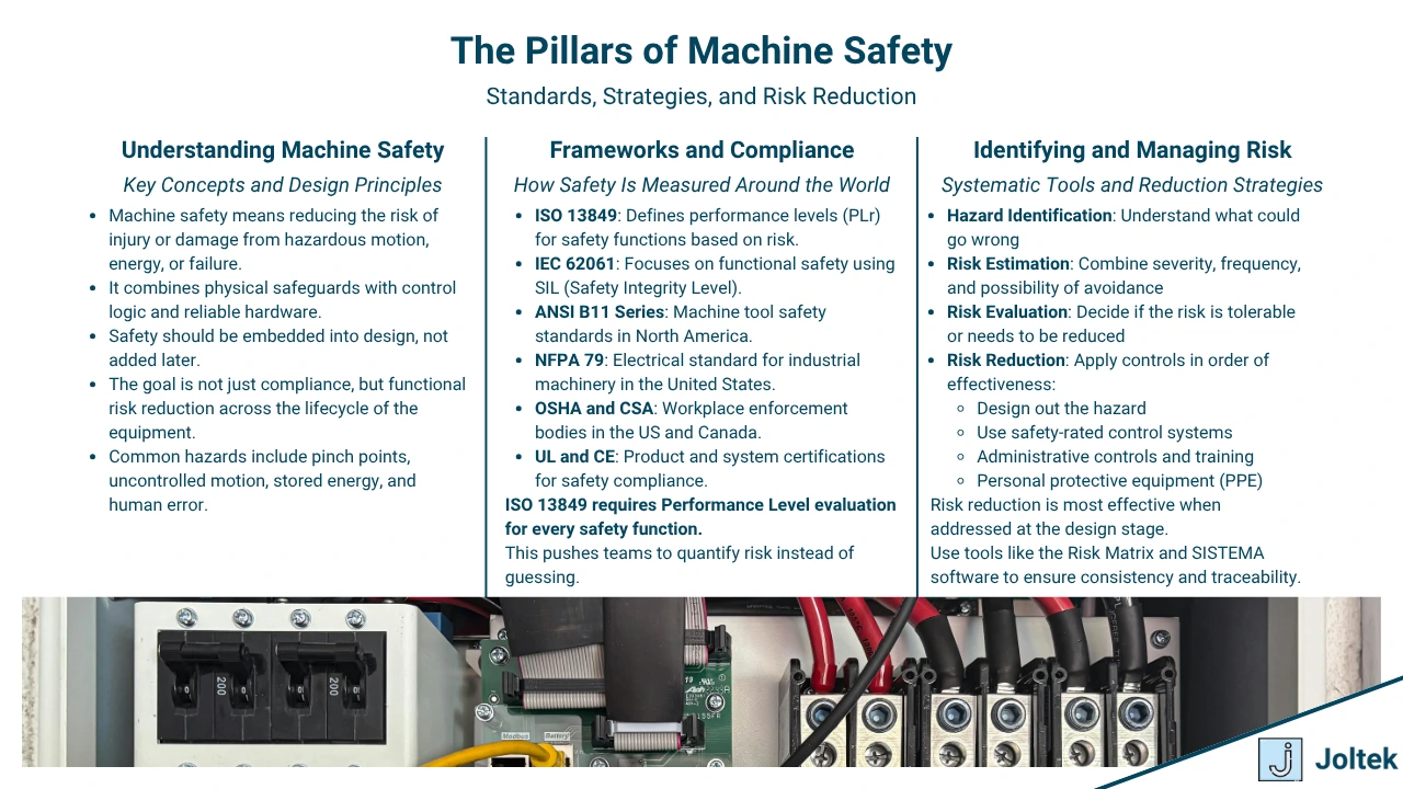
Machine safety is the practice of ensuring that equipment operates without causing harm to people, equipment, or the environment. It is not a single feature or function but a system-wide approach that includes hardware, software, procedures, and behaviors. Machine safety applies across the life cycle of equipment from design and commissioning to routine maintenance and decommissioning. At its core, it is about anticipating potential hazards and building mechanisms that prevent or mitigate those risks without compromising productivity.
Machine safety incorporates several layers of protection. These may include physical barriers, safety-rated devices, control logic, procedures, and operator training. Each layer supports the next, reducing the probability that a single failure could lead to harm. This is sometimes referred to as the hierarchy of controls or the hierarchy of risk reduction.
The hierarchy of risk reduction provides a structured approach to minimizing danger in the workplace. It begins with the most effective strategy, which is to eliminate the hazard entirely. If elimination is not feasible, substitution with a safer alternative is considered. Engineering controls such as physical guards and interlocks follow, then administrative controls like training and procedures. Finally, personal protective equipment (PPE) is the last line of defense. Facilities that rely too heavily on PPE or procedural enforcement without first addressing risk through design often expose their teams to unnecessary hazards.
Safety should be embedded into design from the beginning, not added after the fact. When safety is considered only during installation or commissioning, it often results in compromised solutions that are harder to maintain, less intuitive for operators, and more expensive over time. Safety that is built into the layout, control logic, and operational strategy allows for smoother integration and a more robust manufacturing system overall.
Global safety standards and compliance
Understanding safety standards is essential for both legal compliance and engineering quality. Several global frameworks define requirements for functional safety, hardware design, and verification processes. ISO 13849 is commonly used for machinery safety and focuses on performance levels. IEC 62061 is applied when systems use programmable logic, especially in complex applications involving safety-rated controllers. ANSI B11 provides a comprehensive set of standards for general machinery safety in North America. NFPA 79 outlines requirements for industrial machinery electrical systems and is widely followed in the United States.
In addition to standards, several organizations issue certifications that validate whether a component or system meets applicable safety rules. These include CE marking in Europe, CSA and UL in North America, and OSHA’s regulatory enforcement in the United States. Certifications are not optional in many jurisdictions and often determine whether a machine can be legally operated. They also give engineers and buyers confidence that the equipment has been tested and evaluated for known failure modes.
There is a critical difference between local compliance and global best practices. A plant operating in the United States might only be required to meet OSHA standards, but the same facility may benefit from aligning with ISO 13849 or IEC 62061 if it operates globally or procures equipment from international vendors. Companies that work across borders must harmonize standards to reduce confusion and avoid inconsistent safety levels across locations.
If your team is navigating modernization projects that involve upgrading safety infrastructure, our article on retrofitting legacy equipment outlines common risks and how to address them during implementation.
The risk assessment process
The risk assessment process is the foundation for designing an effective safety system. Before a solution can be developed, it is essential to understand where hazards exist and how they might lead to harm. Risk assessments begin with hazard identification. This includes mechanical risks such as pinch points and rotating equipment, electrical hazards, chemical exposure, ergonomics, and interaction with autonomous systems like robotics or conveyors.
Once hazards are identified, teams must estimate and evaluate the risk based on two key criteria: the severity of potential harm and the likelihood of its occurrence. Evaluating risk allows you to prioritize which hazards must be addressed with engineered solutions and which can be managed through less intensive controls. Without this step, teams often waste resources solving problems that are unlikely to occur while overlooking high-impact threats.
After evaluation, the goal is to reduce risk to an acceptable level using strategies in line with the hierarchy of controls. Engineering solutions are preferred, followed by administrative controls and, as a last resort, PPE. Risk reduction is not a one-time event. Systems and processes must be reassessed when equipment is modified, replaced, or moved.
Several tools and templates can help facilitate this process. One of the most widely used is the Risk Matrix, which plots severity against frequency to assign priority. Another is SISTEMA software, a free tool developed by IFA in Germany that evaluates safety functions and calculates the performance level (PL) of a circuit according to ISO 13849. Using these tools enables more accurate design and documentation of safety performance. They also provide a shared language between designers, technicians, and auditors.
When bringing new systems online or performing major upgrades, including a structured risk assessment is one of the most important steps you can take to reduce liability and protect workers.
Core Safety Hardware Components
Safety relays
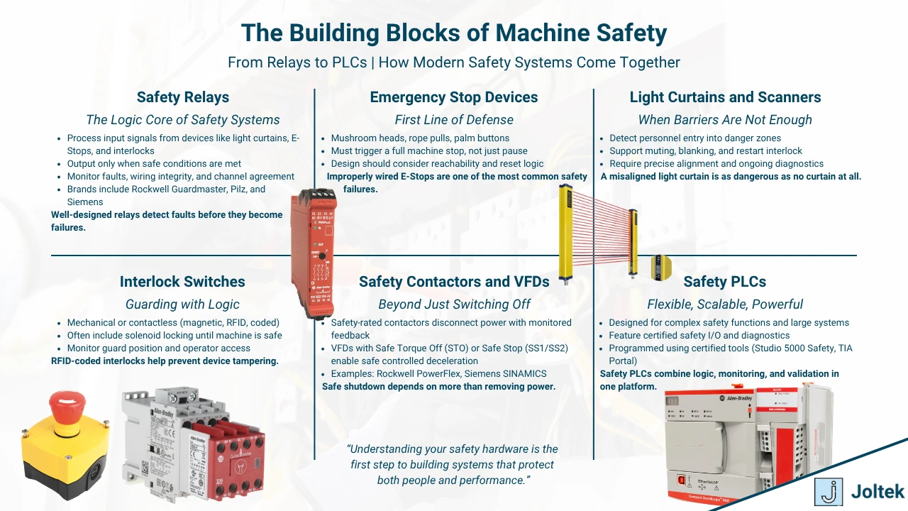
Safety relays are the foundation of hardwired safety control in industrial systems. Their primary function is to monitor safety devices and determine whether it is safe to allow machine operation. They are designed to detect faults in circuits and prevent equipment from restarting until all safety conditions are met. Unlike general-purpose relays, safety relays include redundant and monitored contacts, making them suitable for safety-rated applications.
Inside a safety relay, there are typically two channels that monitor the state of the connected devices. This dual-channel structure ensures that a single failure will not compromise the integrity of the safety circuit. For example, when both channels from an emergency stop or light curtain are closed, the relay energizes its output contacts. If either channel is interrupted, the outputs drop out, de-energizing the machine and removing the hazard.
Many safety relays now offer diagnostic features such as status LEDs, feedback monitoring, and fault codes. Diagnostics help maintenance teams identify wiring issues, misaligned devices, or component failures without lengthy troubleshooting. Advanced relays may also include timing functions, reset logic, or cascading capabilities to integrate multiple zones of safety into a single architecture.
Well-known brands include Rockwell Automation’s Guardmaster line, Pilz’s PNOZ relays, and Siemens’ Sirius modular relays. Each brand provides variants suited for different voltage levels, safety categories, and device compatibility. When selecting a relay, it is essential to verify that the component meets the required Performance Level (PL) or Safety Integrity Level (SIL) for your application.
Emergency stop devices
Emergency stop devices are the most immediately recognized element of any machine safety system. These devices are designed to provide operators with a direct and intuitive way to stop equipment during abnormal or unsafe conditions. While they appear simple, proper selection and placement is critical for safety performance.
There are several types of emergency stop devices. The most common is the mushroom-head push button, which must be manually reset after activation. Rope pull e-stops are used along long conveyors or production lines, allowing access to emergency stop functionality from any point along the line. Palm buttons are used in areas where operators may wear gloves or require large surface area activation.
In selecting and wiring e-stop devices, it is important to distinguish between Category and Performance Level. Category describes the architecture of the safety circuit, while Performance Level reflects the reliability of the function based on diagnostic coverage and component quality. Modern manufacturing environments should aim for Category 3 or higher with Performance Level D or E for emergency stops.
Best practices include placing e-stops within easy reach of all operators, labeling them clearly, and ensuring they are never obstructed by equipment or materials. Every device must be tested regularly and tied into safety-rated relays or safety PLC inputs to ensure proper function.
For more on how safety fits into plant-wide architecture, you can explore the guide to control system modernization.
Light curtains and area scanners
Light curtains are optical devices that create a field of light beams to detect intrusion into a hazardous area. If a beam is broken, the curtain sends a signal to shut down the machine or trigger a stop. These devices are especially useful in applications where physical barriers are impractical, such as robotic cells or material handling zones.
Area scanners function similarly but use rotating lasers to map a two-dimensional zone. They are ideal for mobile robots or areas with dynamic workflows. One of the most useful features of modern light curtains is muting, which allows materials like pallets to pass through without triggering a stop while still protecting workers.
Integration with PLCs and safety relays is straightforward, provided the system supports dual-channel inputs. Most light curtains have a dedicated controller or interface module that handles signal conditioning and status monitoring. Proper alignment, regular cleaning, and mounting at the correct height are essential for consistent performance.
When troubleshooting these devices, common problems include beam misalignment, dirty lenses, cable faults, or incompatible relay logic. Many models include visual indicators for alignment and fault detection, which helps maintenance teams resolve issues without lengthy diagnostics.
Interlock switches
Interlock switches ensure that machine guards, doors, or hatches remain closed while equipment is in motion or energized. These devices can either detect the physical position of the guard or combine position sensing with locking mechanisms.
There are two major types of interlocks. Mechanical interlocks use a keyed actuator that enters the switch body when the door is closed. Non-contact interlocks use RFID or coded magnetic sensors to achieve the same result without physical contact. Non-contact models are ideal for hygienic environments or applications where mechanical wear is a concern.
Guard locking interlocks are used when simply opening a guard is not acceptable until all motion has stopped. These devices physically lock the guard in place using a solenoid or magnetic actuator. They are especially useful in high-inertia applications such as saws or centrifuges where the danger persists even after power is removed.
Door monitoring systems often combine interlocks with LED status indicators and safety relays. Correctly integrating these systems ensures that equipment cannot restart unless all guards are securely closed and in the correct state.
Safety contactors and actuators
Safety-rated contactors are electromechanical switching devices specifically designed for use in safety circuits. They differ from standard contactors by including features such as mirror contacts, forcibly guided contacts, and status feedback that can be monitored by safety relays or PLCs.
These devices are typically installed on the output side of the safety circuit to remove power from motors, heaters, or other actuators when a safety condition is violated. In some systems, they may also be used in series with a VFD to create redundant cutoffs.
Contactors must be chosen based on switching frequency, current load, and safety category requirements. In some cases, a standard contactor may be used if it is installed with redundancy and monitored for fault conditions, but many safety-rated contactors come with certifications that simplify compliance.
Safety actuators can also include pneumatic valves with integrated monitoring, safety-rated servos, and electromechanical brakes. Selection must always account for how the actuator will behave in a fault condition and whether it will bring the system to a safe state.
Safety-rated variable frequency drives
Modern VFDs often include built-in safety functions, reducing the need for external contactors or relays. The most common is Safe Torque Off (STO), which disables the drive’s output stage and prevents torque generation in the motor. STO is used in almost every application where motion must be stopped reliably.
Additional safety functions include Safe Stop 1 (SS1), which decelerates the motor before disabling torque, and Safe Stop 2 (SS2), which maintains torque control until the motor is fully stopped. Other features such as Safe Limited Speed (SLS) and Safe Direction (SDI) are available in more advanced models.
Rockwell’s PowerFlex drives and Siemens’ SINAMICS series both offer safety-integrated models. To use these features correctly, engineers must follow the manufacturer’s wiring and configuration guidelines, including the removal of default jumpers and activation of safety parameters. Failure to do so results in a circuit that appears functional but is not rated for safety.
Safety functions should always be validated during commissioning to ensure they behave as expected under fault conditions. This includes verifying input status, response times, and system behavior during simulated faults.
Safety programmable logic controllers
Safety PLCs extend the functionality of traditional PLCs by including dedicated safety logic and dual-redundant processing. They are used in systems that require complex safety logic, zoning, or integration with distributed I/O. Unlike standard PLCs, safety PLCs include locked memory areas, certified function blocks, and restricted programming tools to prevent unauthorized changes.
Safety I/O cards include dual-channel inputs and test pulse monitoring to ensure integrity. Outputs are often designed with fault detection and confirmation capability. These cards are not interchangeable with standard I/O and must be installed with careful attention to configuration and diagnostics.
Programming environments such as Rockwell’s Studio 5000 Safety Edition or Siemens’ TIA Portal with safety extensions offer certified libraries and validation tools. This allows engineers to design, simulate, and validate safety functions with a clear path to compliance. However, the flexibility of software also introduces new risks. Programming errors, incorrect logic, or unverified changes can undermine the safety function entirely.
When using a safety PLC, every aspect of the system must be documented and validated. This includes wiring diagrams, logic programs, network configurations, and I/O verification. Safety PLCs provide unmatched flexibility and scalability, but only when implemented by engineers who fully understand their capabilities and limitations.
Safety Circuit Design Principles
Single versus dual channel design
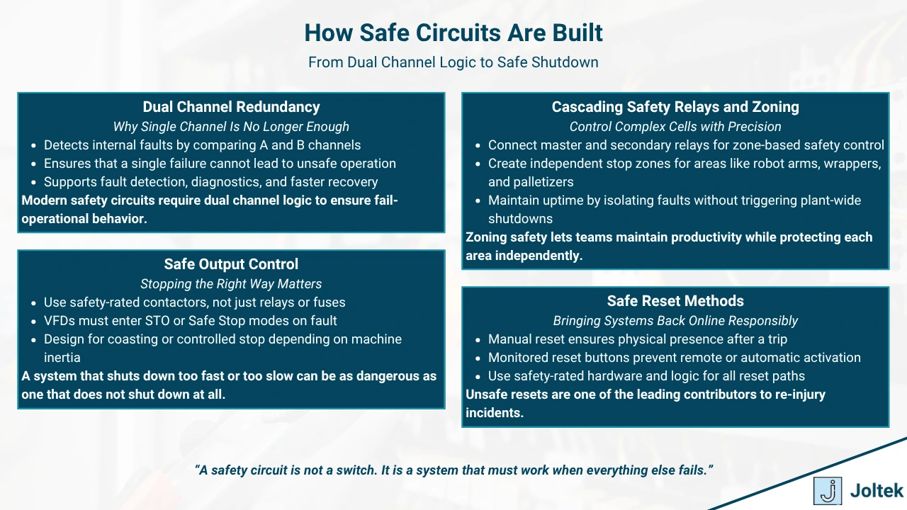
Single channel safety circuits are no longer acceptable in most modern industrial applications. These systems rely on a single line of control to monitor safety devices, which creates a single point of failure. If a wire breaks or a contact welds closed, the circuit can falsely indicate a safe condition. This undermines the purpose of the safety system and puts personnel and equipment at risk.
Dual channel design solves this issue by requiring two independent paths to confirm that conditions are safe. Each channel monitors its own line of input from safety devices such as emergency stops, light curtains, or interlock switches. The key benefit of dual channel design is its ability to detect faults, including cross shorts, open wires, and mismatched input states. If either channel fails or produces a different result, the system will enter a fault condition and disable outputs.
This design is now required to achieve higher Performance Levels as defined in ISO 13849. Category 3 and Category 4 circuits both rely on redundancy and fault detection, which can only be achieved with dual channel architecture. Dual channel safety provides a level of diagnostic coverage that allows operators to trust the system and resolve problems before accidents occur.
Cascading safety circuits
Cascading safety circuits allow multiple safety zones to be monitored and controlled in a structured way. Instead of running all devices into a single safety relay, multiple relays can be linked together to build modular logic. This is often done through master and secondary configurations, where one relay controls overall logic while others manage local devices.
In a master relay configuration, the primary relay receives input from each downstream zone and only energizes the outputs when every connected zone is confirmed safe. The secondary relays handle devices within a specific zone, such as a robotic cell, stretch wrapper, or conveyor segment. This modular approach simplifies troubleshooting, reduces downtime, and enables better visibility into which area is preventing startup.
Zoning is particularly important in larger or more complex applications. A palletizing cell, for example, might have its own light curtains, interlocks, and emergency stops separate from the adjacent conveyor zone. By using cascaded circuits, engineers can allow some zones to operate independently while others are locked out based on local risks.
This type of segmentation also supports staged startup and shutdown sequences, improving workflow efficiency without compromising safety. For more on how safety fits into end-to-end control strategies, explore the automation system architecture article.
Safety circuit reset logic
The reset function is one of the most misunderstood elements of safety circuit design. After a fault is cleared, the circuit often requires a manual reset before allowing the machine to restart. This prevents unintended motion and gives operators time to inspect the area for residual risks.
Manual resets are implemented using a normally open push button that completes a monitored circuit only when pressed. Safety relays and safety PLCs typically evaluate this signal and only accept it if all other conditions are safe. Automatic reset is discouraged in most applications because it reactivates the machine as soon as a fault clears, which can lead to unexpected motion and serious injury.
For a reset function to be considered safety-rated, it must be connected to the appropriate channels, monitored for faults, and tested periodically. Improperly wired resets or unmonitored switches can lead to unsafe restart conditions, even when all devices appear functional.
Common faults in reset logic include stuck buttons, bypassed wiring, or improperly programmed delays. In dual channel systems, each reset input must be verified independently. Visual indicators, such as LEDs on safety relays, help confirm that both the device state and the reset command are valid.
Output side considerations
Safety does not end at the input side of a circuit. The output side must also be designed to bring the system to a safe state during faults. This includes ensuring that actuators, drives, motors, or heaters are shut off completely and remain off until a safe condition is restored and a reset is received.
A safe output is one that disconnects all hazardous energy reliably and predictably. In most systems, this is achieved through safety-rated contactors, STO-capable VFDs, or power disconnects. Outputs must be designed to remove energy without creating new hazards, such as free-falling loads or uncontrolled deceleration.
The difference between safety-rated and standard outputs lies in their behavior during fault conditions. Safety-rated devices provide feedback, monitoring, and fail-safe behavior. For example, a contactor with forcibly guided contacts ensures that a welded contact is detected and triggers a fault. A VFD with Safe Torque Off disables the output transistors completely, guaranteeing no torque can be generated.
Engineers must also consider how the system stops. In some applications, a controlled stop is required to avoid damaging products or machinery. This involves allowing the motor to ramp down before disconnecting power. In other cases, a coast to stop is acceptable. Emergency shutdowns must be fast, predictable, and tested regularly to ensure functionality.
In advanced systems, the behavior of each output device during shutdown must be documented and validated. This includes settings inside drives, configurations in PLC logic, and wiring of feedback circuits. A well-designed output section ensures that safety extends all the way to the last physical component in the system.
Modern Approaches to Safety Integration
Distributed safety over Ethernet IP and PROFINET
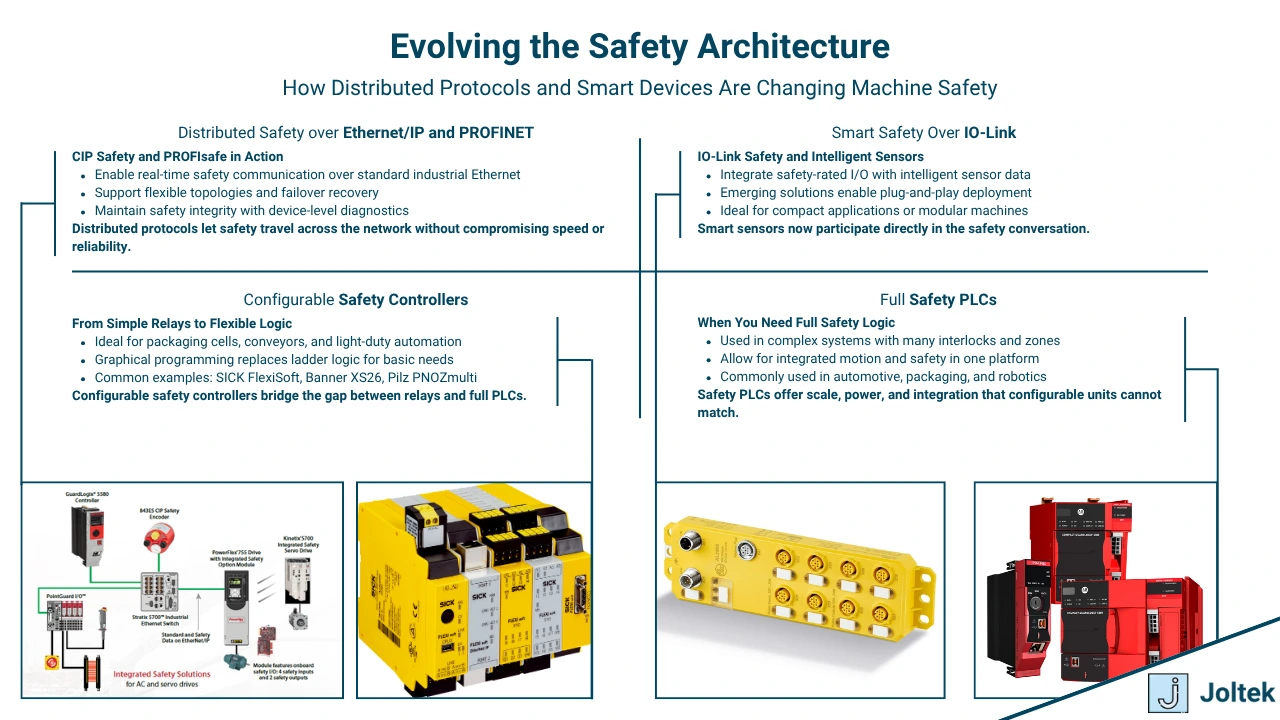
Distributed safety architectures allow safety signals to travel across industrial networks, offering flexibility that hardwired systems cannot match. Technologies such as CIP Safety over Ethernet IP and PROFIsafe over PROFINET enable safety-rated communication between controllers, distributed I O modules, and end devices using standard networking infrastructure. These systems maintain compliance with functional safety standards while dramatically reducing wiring complexity and enabling modular designs.
CIP Safety and PROFIsafe work by embedding safety data within standard Ethernet packets but with added integrity checks, redundancy, and time stamping. What makes these protocols safety-rated is not the physical medium, but the layered approach to error detection, confirmation, and fault tolerance. They verify that safety messages are received exactly as sent, within defined timing constraints, and from authenticated sources. If these conditions are not met, the system initiates a safe shutdown.
Determinism and latency are valid concerns when safety messages share a network with standard control traffic. Modern switches and controllers use prioritization mechanisms and dedicated safety processing to ensure timely and deterministic delivery. Failover handling is also built into these protocols. If communication is lost, devices will enter a predefined safe state after a configurable timeout period.
This approach is ideal for large systems with multiple zones, mobile equipment, or modular machinery that requires frequent reconfiguration. Limitations include the need for certified devices, increased validation effort during commissioning, and a strong understanding of networking fundamentals. While distributed safety offers enormous benefits, it must be designed carefully to avoid unintended consequences when segments of the network fail.
For a broader view on how industrial networks are evolving, including the role of Ethernet IP in control systems, explore the article on industrial networking fundamentals.
Safety over IO-Link and other protocols
IO-Link Safety is an emerging extension of the IO-Link standard that brings safety functionality to intelligent sensor networks. This protocol allows devices like safety light curtains, door switches, and emergency stops to communicate both standard and safety data to a controller over the same three-wire cable used in traditional IO-Link.
One of the main advantages of IO-Link Safety is the ability to gather diagnostics and configuration data from devices while still maintaining safety integrity. Smart sensors can report internal faults, alignment issues, or miswired connections without disrupting the safety function itself. This level of transparency reduces downtime and accelerates troubleshooting.
Integration with smart sensors means safety functions can be managed alongside process data, enabling more flexible machine control strategies. For example, a light curtain may send both a safety stop signal and a real-time count of parts passing through its field. This dual-function capability allows systems to remain efficient without sacrificing protection.
Adoption of IO-Link Safety is still in its early stages, and device availability is limited compared to traditional Ethernet IP or PROFINET-based solutions. However, for OEMs and machine builders seeking high-performance diagnostics in compact packages, IO-Link Safety will likely become a key component of future system design.
Configurable safety controllers versus safety PLCs
Configurable safety controllers fill the gap between basic safety relays and full safety PLC systems. These devices offer programmable logic for simple applications using a graphical interface without requiring PLC programming skills. Examples include the Sick FlexiSoft and Banner XS26 platforms, which allow engineers to define logic using drag-and-drop function blocks.
These controllers are ideal for small to medium systems that need more flexibility than a hardwired relay but do not justify the complexity of a full PLC. Use cases include packaging lines, small robotic cells, and automated assembly stations. Configurable safety controllers can monitor multiple safety inputs and create conditional outputs based on logic rules, timing, or reset conditions.
The choice between a configurable controller and a safety PLC comes down to scale and complexity. When a system involves multiple zones, distributed I O, integration with motion control, or networked safety devices, a safety PLC becomes the better choice. Safety PLCs provide greater flexibility, support advanced diagnostics, and allow tighter integration with plant-wide automation platforms.
It is important to note that while configurable controllers simplify deployment, they still require careful design and validation. All safety logic, regardless of the platform, must be verified against the risk assessment to ensure that intended behavior matches actual functionality under fault conditions.
For teams considering upgrades to their safety architecture, this decision often comes as part of a broader automation strategy. If your facility is evaluating modernization or expansion, our article on how to approach manufacturing upgrades offers guidance on aligning technology decisions with operational goals.
Common Pitfalls and Misconfigurations
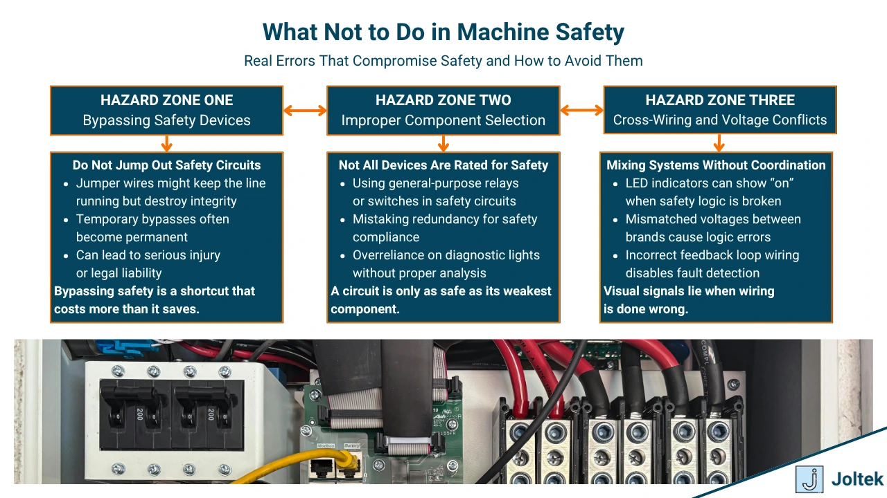
Bypassing safety devices
Bypassing safety devices creates a false sense of control and introduces real danger into the workplace. In many plants, technicians or operators will temporarily override a safety device during troubleshooting or commissioning. This may involve shorting inputs, defeating light curtains, or jumping interlocks to keep the line running. While it may appear harmless in the moment, these practices frequently become normalized and are rarely removed once the issue is resolved.
Temporary overrides may be useful when carefully managed under strict lockout and documentation procedures. However, the shift from a temporary measure to a permanent hack often goes unnoticed. Over time, these shortcuts become standard practice, leaving critical systems vulnerable to failure with no protection in place. The danger of jumper wires is that they eliminate the ability of a circuit to detect unsafe conditions while still appearing to function normally.
Jumpering across safety channels, fooling a light curtain controller with a spoofed signal, or taping down e-stop buttons are all examples of actions that can bypass the safety system entirely. Once a circuit is fooled into thinking everything is okay, it cannot protect personnel from real hazards.
From a legal and ethical standpoint, these workarounds can have devastating consequences. If an incident occurs and an investigation reveals that safety systems were bypassed, liability may extend to supervisors, engineers, and even senior leadership. Bypassing safety devices puts lives at risk and places the organization in legal jeopardy, regardless of intent.
Improper component selection
Choosing the wrong hardware is one of the most common root causes of safety failures in automation projects. In many cases, components that look the same as safety-rated versions are used by mistake or to reduce cost. These might include generic push buttons instead of e-stop certified devices, standard relays in place of safety relays, or conventional PLCs in place of safety-certified controllers.
Non-rated hardware may function identically in normal operation but lacks internal redundancy, mechanical guidance, or test pulses required to detect faults. Just because a device behaves the way you expect does not mean it meets the requirements of a safety function.
Another common mistake is confusing redundancy with safety. Two relays in parallel are not a safety system unless they are properly monitored, tested, and certified. Redundancy without diagnostics is not sufficient to detect faults or meet Performance Level requirements.
Diagnostic feedback from a device can also be misleading. Some operators assume that if a contactor or sensor is providing LED feedback, it must be working correctly. But these indicators only show status, not safety compliance. Mistaking diagnostic lights for functional safety can lead to complacency and unverified assumptions about system integrity.
This is especially important when working with programmable safety systems or smart devices. If your team is selecting hardware for a project, refer to your risk assessment, system documentation, and the appropriate performance level requirements before approving components. When in doubt, consult the manufacturer's functional safety manual or third-party certification.
Cross-wiring and voltage mismatches
Incorrect wiring practices are one of the leading causes of hidden safety circuit failures. These errors often pass initial testing but create vulnerabilities that go undetected until a failure occurs. Cross-wiring occurs when input or output lines are routed incorrectly, allowing current to flow in unintended ways or bypassing parts of the circuit.
Many safety relays and controllers rely on specific voltage levels to detect the health of the system. For example, one channel may send out 24 volts while the other sends 19 volts. If wires are crossed or jumpers are installed between these channels, the relay will reject the signal or enter a fault state. This is a protective mechanism to detect out-of-sequence feedback, but it only works if wiring follows exact specifications.
Misleading LED indicators further complicate the issue. A light may turn on even when the signal is incorrect or insufficient to meet the criteria for a safe state. This causes operators to assume that the system is ready, even though the underlying conditions are not met.
Another issue is voltage mismatches across different brands or configurations. Relays and safety devices from different manufacturers often use different test signals or voltage thresholds, which can cause compatibility issues if not properly accounted for. Always validate voltage levels during commissioning and ensure all devices are compatible with the expected signal profiles.
Correct wiring in safety circuits is not just about making electrical connections. It is about creating a fault-tolerant communication path that reflects the true state of the system at all times. If your project involves mixed-brand components or legacy equipment, it is even more important to verify signal integrity and check the circuit against original documentation.
For examples of common design mistakes and strategies to avoid them, explore the equipment modernization article which includes scenarios where wiring and hardware compatibility often lead to safety risks.
Troubleshooting Safety Circuits
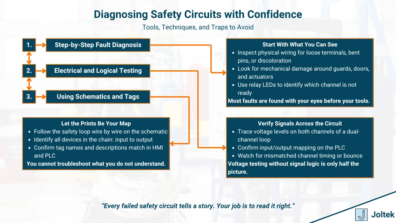
Step by step fault diagnosis
Effective troubleshooting starts with a structured and repeatable approach. Many safety-related faults appear intermittent or obscure but can often be traced back to a small number of root causes. The first step is always a physical inspection. Look for damaged wiring, loose connectors, tripped e-stops, or obstructed light curtains. Pay close attention to mechanical components such as door interlocks or keyed switches that may not be seated properly.
Voltage tracing and channel comparison come next. Most safety circuits operate on 24 volts direct current and rely on consistent readings across both channels of a safety relay. If you measure 24 volts on one channel and zero on the other, you have a fault or an open in the safety loop. Using a multimeter, start at the safety relay and work your way back through each device to determine where the voltage is dropping.
LED status indicators on relays, PLCs, and smart devices provide valuable clues. These indicators often show whether inputs are received, whether channels are consistent, and whether a fault has been latched. Learn the LED logic specific to your hardware platform, as each manufacturer uses its own signaling patterns. Blinking codes, color shifts, or status sequences can quickly point to wiring errors or missing feedback signals.
If your system includes distributed I O or smart safety devices, check communication status and make sure that networked devices are online and verified. Communication faults can mimic device failures, especially when outputs are interlocked to remote inputs that are unavailable.
Using electrical schematics effectively
Electrical schematics are your map to understanding and resolving safety circuit issues. Without them, you are working blind. Every safety circuit should be documented with up-to-date, legible schematics that reflect the current installation. The best troubleshooting process starts by reviewing the schematic before touching any wires.
There are several key symbols to know when reading safety schematics. These include normally open and normally closed contacts, safety relays, dual-channel inputs, and monitored outputs. Symbols for safety-rated devices often include identifying marks or part numbers that distinguish them from standard components. Familiarity with these symbols allows you to trace the logic of the circuit and understand what each component is doing.
To follow the safety chain, begin at the inputs and trace the signal path through to the relay or PLC. Note any branching paths or conditions that might interrupt continuity. A light curtain with a mute input, for example, may appear closed on the diagram but not operate unless the mute is active. Understanding the conditional logic represented on the schematic is critical for diagnosing why a circuit is not ready.
Good documentation includes tagging and version control. Each device, terminal, and wire should have a unique identifier that matches the schematic. When tags are missing or inconsistent, troubleshooting becomes exponentially harder. Best practices include using terminal blocks with labeled wiring, printing control panel layouts, and maintaining revision history when modifications are made.
When commissioning or updating safety systems, ensure that updated schematics are provided to maintenance teams and stored both physically and digitally. If you are working on an upgrade project, the article on control panel best practices includes guidance on wiring standards and documentation strategies.
Practical tools and techniques
The right tools can dramatically reduce the time and risk involved in troubleshooting safety circuits. A basic multimeter is essential for measuring voltage levels and continuity. In safety systems, you will frequently use it to confirm 24 volt supply levels, verify channel integrity, and detect wiring faults.
For more advanced systems, portable safety testers and simulators are invaluable. These tools allow you to simulate device inputs without engaging the actual equipment. Using a simulator to mimic a properly functioning light curtain or e-stop can help isolate whether the issue lies in the device or the wiring.
Another critical tool is a handheld label printer. Keeping devices, wires, and terminals properly labeled helps both in the moment and for future maintenance. Labels should include device tags, input or output references, and date codes if possible. Visual clarity in the panel leads to faster diagnostics and fewer mistakes.
During any diagnostic activity, lockout and tagout procedures must be followed without exception. Testing safety circuits should never be done under live production conditions unless all hazardous motion and energy sources are fully isolated and documented. Use lockout kits, personal tags, and verification checklists to protect everyone involved.
These tools and techniques are not only about speed. They are about confidence. When systems are down or faults are disrupting operations, a structured approach using the right tools builds trust between engineers, technicians, and operations teams. The ability to troubleshoot safely and effectively is a key capability in any modern manufacturing environment.
Commissioning and Validation
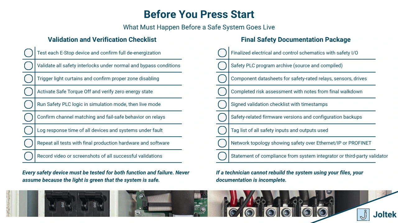
Safety validation and verification
Validation is not a suggestion. It is a requirement for putting a safety system into service. Before startup, every safety function must be verified to perform exactly as intended under normal and fault conditions. This includes both the functional behavior of devices and the integrity of the entire circuit.
Functional testing ensures that each input triggers the correct output response. For example, pressing an e-stop must de-energize the outputs and prevent restart until a reset is performed. Blocking a light curtain should stop hazardous motion and keep it stopped until the area is cleared. Compliance testing, on the other hand, goes deeper by confirming that the entire system meets the risk reduction goals outlined in the design. This involves checking wiring, evaluating safety logic, and reviewing documentation to align with standards such as ISO 13849 or IEC 62061.
In some cases, third-party validation is necessary. Certifying bodies such as TÜV, UL, or CSA may be required to validate safety systems for legal compliance or corporate policy. These validations add an additional layer of accountability. Third-party validation ensures the design meets the performance level requirements through independent review, functional tests, and audit trails.
If your system integrates advanced technologies such as distributed safety or software-defined logic, external validation can also help identify edge cases or design oversights that internal teams may have missed. For critical infrastructure, product recalls, or international deployments, third-party involvement is a best practice.
Safety documentation and change control
Proper documentation is what gives a safety system its credibility and longevity. Without it, future troubleshooting, audits, or upgrades become difficult and error-prone. Every safety system should have a complete validation checklist that walks through each function, confirms test results, and includes signatures from the responsible parties. These checklists act as both commissioning records and legal protection in the event of future investigations.
Wiring diagrams must be clear, current, and reflect the actual installation. Component datasheets should be included in the safety file to verify certifications and specifications. Most importantly, the original risk assessment must be stored and updated as conditions change. A functioning safety system is only as good as the traceability behind it. If you cannot prove that a safety function was tested and approved, you may be liable if it fails.
Management of Change procedures are essential for maintaining safety over the life of a system. Every modification, whether physical or logical, must go through a formal review process. This includes additions to safety logic, rewiring of inputs or outputs, firmware updates, and changes to mechanical guarding. Without a proper MOC process, even small changes can unintentionally disable or compromise critical protections.
If your plant is undergoing a retrofit or digital upgrade, these documentation practices are even more important. For guidance on integrating change control into broader improvement projects, see the article on how to approach manufacturing upgrades.
Documenting safety is not just for engineers. It is a tool for operators, maintenance staff, auditors, and future project teams to understand how the system works and how to keep it working. Properly commissioned safety systems are not only more reliable. They are easier to support, easier to scale, and more trusted by the people who rely on them every day.
Safety Beyond Hardware
Safety culture in manufacturing
A strong safety culture is more important than any single device or circuit. While relays, sensors, and controllers form the backbone of physical safety systems, it is the attitudes and behaviors of the people who work around them that ultimately determine how effective those systems are. In many facilities, technical solutions are put in place but are routinely overridden, ignored, or misunderstood. This disconnect usually points to a lack of buy-in across departments.
Training is the foundation of culture. Operators must understand not only how to use equipment safely but why certain systems exist. Maintenance teams need to be familiar with safety logic, diagnostics, and proper troubleshooting techniques. Engineers must design systems with practical use in mind and clearly communicate intent. Cross-functional training ensures that everyone shares responsibility for maintaining safe operations.
To reinforce a safety-first mindset, companies must track the right metrics. Safety metrics and KPIs should go beyond basic incident rates and include proactive measures such as participation in safety meetings, completion of safety training, and response time to safety-related work orders. What gets measured gets managed, and what gets celebrated gets repeated.
Near-miss reporting and routine audits are also essential. A near-miss is a valuable opportunity to correct a weakness before it becomes an incident. Encouraging transparent reporting, without fear of blame, builds trust and leads to meaningful improvements. Audits—both internal and third-party—should validate not just hardware but documentation, procedures, and overall culture.
For additional insight into building sustainable programs that involve both technical and human elements, visit the article on manufacturing consulting frameworks, which covers how leadership, process, and technology must align.
Human factors and ergonomics
Designing for safety means designing for real people, not just compliance checklists. Many safety-related incidents happen not because a system failed, but because it was awkward, frustrating, or confusing to use. When machines are difficult to interact with, operators are more likely to take shortcuts that increase risk.
Human factors should be considered from the earliest stages of design. This includes the placement of e-stops, the visibility of indicators, the size and responsiveness of buttons, and the ease of access for tasks like cleaning or setup. A system that accounts for human behavior is more likely to be used correctly and consistently.
Ergonomics plays a key role in preventing long-term injuries and improving day-to-day safety. Repetitive tasks, awkward reaches, or excessive force requirements all contribute to strain that can lead to musculoskeletal issues or fatigue. Fatigued workers are more prone to mistakes, and in safety-critical environments, small mistakes can have serious consequences.
Accessibility should be built into interfaces and control panels. Labels should be readable from a distance. Touchscreens should respond to gloved hands. Feedback should be unambiguous. Designing with the operator in mind not only reduces injuries, it improves productivity and morale.
Cybersecurity and safety interlock
As more safety systems become network-connected, cybersecurity becomes a direct safety concern. Traditional safety systems were isolated and hardwired. Today, many facilities use distributed safety over Ethernet or rely on programmable safety logic that is connected to the broader plant network. This creates new vulnerabilities that must be addressed.
When a safety PLC or relay is exposed to the network, it becomes a potential target for unauthorized access or unintentional modification. Firmware updates, remote configuration tools, or even simple tag changes can alter the behavior of safety functions. The risk of unauthorized changes is real and growing, especially in facilities with shared IT and OT infrastructure.
To manage this risk, teams must implement network segmentation and access controls. Safety devices should reside on protected network zones, separated from standard control traffic. Changes to logic or configuration should require secure authentication, logging, and formal approval. Monitoring traffic for unusual behavior or attempted access is essential in modern industrial systems.
Security audits should include not only firewalls and patching strategies but also a review of who has access to safety logic, how often it is modified, and how those changes are tracked. The convergence of IT and OT has many benefits, but it requires a new approach to governance.
For an in-depth look at how these topics intersect with control architecture and operational risk, refer to the article on cybersecurity in manufacturing, which includes examples of safety implications tied to unsecured networks.
Future Trends in Industrial Safety
AI and computer vision for safety detection
Artificial intelligence is expanding the boundaries of what safety systems can detect and respond to. Traditional safety devices rely on binary conditions—such as whether a door is open or a beam is broken. AI-powered vision systems, by contrast, can interpret complex visual scenes, identify unsafe behaviors, and adapt to changing environments in real time.
These systems are already being used to detect PPE compliance, monitor unsafe postures, and identify intrusion into restricted areas without requiring physical guarding. The ability to continuously monitor activity and context means these tools can complement hardware-based safety by adding a new layer of situational awareness. AI does not replace traditional safety systems, but it adds intelligence where hardwired logic alone would be too rigid.
However, AI-based safety tools require robust training, high-quality video inputs, and clearly defined response protocols. False positives or missed detections can undermine trust and limit adoption. As the technology matures, expect to see hybrid systems where safety relays work alongside AI platforms to manage risk more effectively.
Digital twins and virtual commissioning for safety validation
Digital twins are changing the way safety systems are designed, tested, and validated before physical deployment. A digital twin is a dynamic software model of a machine, cell, or process that mirrors its behavior in real time. When combined with virtual commissioning, it enables teams to simulate safety scenarios, validate interlocks, and test logic without needing access to live equipment.
This approach allows engineers to identify issues such as incorrect reset logic, missing e-stop conditions, or improper zoning before any wiring takes place. Simulating safety events in a digital twin reduces startup time, improves confidence, and lowers the risk of costly rework on the plant floor.
In highly automated environments, virtual commissioning is also used to coordinate safety zones with robotics, conveyors, and motion control systems. It enables collaboration between design teams, safety engineers, and integrators even before the equipment arrives on site. When properly implemented, these models can also support ongoing diagnostics and predictive maintenance post deployment.
Cloud-connected safety diagnostics and analytics
Cloud integration brings new possibilities for monitoring, analyzing, and improving safety systems over time. Safety PLCs, smart relays, and distributed I O devices can now push data to cloud platforms that aggregate performance metrics, fault history, and device health information.
This allows maintenance and safety teams to spot trends across multiple facilities, identify devices that are frequently triggering faults, and take proactive action before failures occur. Cloud-connected diagnostics turn safety into a continuous improvement opportunity instead of a reactive task.
Examples include tracking e-stop activations, logging reset delays, or monitoring the frequency of light curtain interruptions. Over time, this data can highlight operator behavior, layout inefficiencies, or hardware degradation. While data alone does not improve safety, the ability to act on trends and insights at scale represents a major shift in how safety is managed.
Cloud-based tools also support remote audits, compliance tracking, and automated documentation, which are especially valuable for multi-site manufacturers with limited on-site resources.
For manufacturers already implementing cloud-based control and visualization, the article on modern SCADA architecture explores how edge-to-cloud connectivity is reshaping industrial data strategies, including safety applications.
Collaborative robot safety standards and sensing
Collaborative robots are redefining safety by allowing humans and machines to work side by side without full physical separation. Cobots are designed to operate at safe speeds, apply limited force, and stop automatically when contact is detected. This eliminates the need for large cages or hard guarding in many applications.
To support this shift, new standards such as ISO 10218 and ISO TS 15066 define how cobots must behave, what sensing they must include, and how risk should be assessed. Safety strategies include built-in force and torque sensors, vision-based speed control, and dynamic zoning to reduce risk as human proximity changes.
Cobot safety is not just about device features. It depends heavily on how the robot is applied, programmed, and supervised. A poorly integrated cobot can become more dangerous than a traditional robot if safety considerations are overlooked during deployment.
In practice, most cobot applications still require some form of risk reduction, whether through soft barriers, area scanners, or clearly defined task limits. Proper documentation, risk assessment, and commissioning are just as important with cobots as they are with traditional systems.
As sensing improves and standards continue to evolve, expect to see broader adoption of collaborative robotics in manufacturing, warehousing, and inspection tasks. These systems offer flexibility and efficiency, but only when deployed with a full understanding of their safety requirements.
Case Studies and Real-World Scenarios
Common mistakes seen in the field and how they were fixed
Many safety issues in industrial environments do not stem from a lack of investment but from misapplied solutions. One of the most frequent mistakes is assuming that an e-stop or light curtain alone is enough to meet the required performance level. In one case, a packaging line was fitted with e-stops that were not dual channel and had no feedback monitoring. The circuit would appear functional, but any fault in the wiring or contact would leave the equipment in a false-safe state.
This was resolved by upgrading to dual-channel e-stops, wiring them through a certified safety relay, and adding status indicators that provided visual confirmation of each input. The key insight was that visible function is not the same as validated safety.
In another facility, a conveyor zone had repeated issues with light curtains being bypassed using reflective tape during maintenance. Operators were under pressure to maintain throughput, and workarounds became normalized. The solution involved retraining the team, installing a proper muting configuration with stack light indication, and implementing a safety interlock that required supervisor override for bypass. Fixing cultural habits required both technical adjustments and process ownership.
If you are navigating similar implementation gaps, the article on modernizing control systems includes additional examples of common pitfalls and how to structure recovery plans for safety and automation issues.
Safety retrofits in legacy equipment
Retrofitting safety into legacy systems presents one of the most complex challenges in industrial automation. These systems often lack documentation, use obsolete components, and were never designed with safety standards in mind. However, with the right approach, even decades-old equipment can be brought into compliance without major mechanical changes.
A legacy palletizer in a food plant had no integrated safety logic, relying solely on a main disconnect and two non-rated e-stops wired to standard relays. To bring the system up to standard, the team installed a safety-rated PLC, added dual-channel e-stops, and integrated perimeter light curtains. Instead of rebuilding the panel, the team used a separate safety circuit wired in parallel to monitor hazardous zones and remove power via a redundant contactor.
The insight here was to decouple safety control from machine control without interfering with the original logic. This allowed the machine to retain its proven sequence but respond appropriately to safety violations with rapid, verifiable shutdowns.
Another example involved retrofitting guarding to a batch mixer that had open access to moving shafts. Non-contact interlocks were installed with a mechanical override for cleaning, combined with timed resets and supervisor acknowledgment. The solution met audit requirements while maintaining operational flexibility.
Retrofitting often demands creativity, layered protections, and compromise. Documentation, validation, and operator training are just as important as the hardware. Small steps, when taken methodically, can create large safety improvements in aging facilities.
Greenfield safety design for new lines and robotic cells
Designing safety from a blank slate allows for more elegant, integrated, and cost-effective solutions. In a recent greenfield robotic palletizing cell, the design team implemented distributed I O for safety, tying in light curtains, door interlocks, and emergency stops across three zones. Instead of running all wiring back to a central panel, localized nodes reduced cabling and improved serviceability.
The safety PLC was programmed to monitor each zone independently, allowing operators to access one section for restocking without shutting down the entire line. This zoning approach not only improved uptime but also made fault identification faster and more transparent.
In a separate project involving a high-speed bottling line, the entire safety system was simulated and validated using a digital twin prior to installation. This allowed the team to test e-stop behavior, interlock logic, and reset sequences virtually. When the equipment arrived on site, commissioning time was reduced by more than fifty percent and no safety-related rework was required.
Designing for safety in new installations is not just about meeting code. It is about aligning safety with operational goals. Considerations include how operators interact with the equipment, how maintenance will be performed, and how incidents will be investigated.
Successful greenfield safety projects reflect clear communication between engineering, operations, and integrators. When done well, they create systems that are safer, easier to use, and more adaptable for future growth.
FAQs
When do I need a safety PLC versus a safety relay
A safety relay is ideal for simple applications, while a safety PLC is necessary for complex or scalable systems. If your safety requirements are limited to a few inputs and outputs, such as an e-stop and a light curtain on a single machine, a hardwired safety relay is often the simplest and most reliable choice. It requires no programming, offers high reliability, and is easy to troubleshoot.
However, when your application involves multiple zones, programmable logic, integrated diagnostics, or networked safety devices, a safety PLC becomes the better fit. Safety PLCs can monitor dozens or hundreds of inputs, manage interlocks across multiple machines, and provide detailed diagnostics. The core insight is that safety relays are best for fixed logic, while safety PLCs support dynamic logic and distributed systems.
If your project involves integration between safety zones, motion control, and remote access, the flexibility of a safety PLC can significantly reduce wiring, commissioning time, and long-term maintenance. In large systems, safety relays can become difficult to scale, and changes often require rewiring. With a safety PLC, logic can be updated in software with proper validation and access controls.
Can I use Ethernet for safety
Yes, Ethernet can be used for safety as long as it is paired with a certified safety protocol. Standard Ethernet alone does not provide the timing guarantees or integrity checks required for safety-rated communication. However, protocols such as CIP Safety over Ethernet IP or PROFIsafe over PROFINET add those layers of protection.
These protocols allow safety messages to travel over the same physical networks used for control and monitoring. They include built-in checksums, sequence numbers, timeouts, and redundancy to ensure that commands are accurate, delivered on time, and not tampered with. Using Ethernet for safety enables modular architectures and reduces wiring, but it requires careful design, segmentation, and validation.
It is also important to understand that only certified devices can be used within these systems. Each endpoint, such as a remote I O module or safety controller, must support the safety protocol and be configured to respond appropriately under fault conditions. Ethernet-based safety is common in modern factories but must be implemented following strict guidelines to maintain compliance and integrity.
What is the difference between STO and SS1
Safe Torque Off (STO) and Safe Stop 1 (SS1) are both safety functions used in variable frequency drives, but they serve different purposes. STO disables the drive’s ability to generate torque by removing power from the output stage. This is an immediate and absolute stop, used when it is necessary to eliminate any chance of motion.
SS1, on the other hand, allows the motor to decelerate in a controlled fashion before torque is safely removed. It is typically used in high-inertia systems where an immediate stop could cause mechanical damage or safety hazards. The key insight is that STO cuts power instantly, while SS1 applies a managed stop followed by STO.
In practical terms, STO is used when safety requires an immediate shutdown, such as when a door is opened or an e-stop is pressed. SS1 is useful when the process must come to a stop quickly but in a coordinated and predictable way. Some systems may use both depending on the risk assessment and application requirements.
If you are working with modern drives, such as the PowerFlex 525, understanding how these functions are wired and configured is essential. For a detailed walkthrough of real-world safety applications involving VFDs, see the industrial safety video article, which covers drive safety inputs and circuit behavior.
Can safety be achieved purely through software
Safety cannot be achieved through software alone without certified hardware components. While software plays a crucial role in managing logic, conditions, and interlocks, the physical inputs and outputs involved in safety must be connected to safety-rated hardware. This includes dual-channel I O, safety relays, contactors, and certified sensors.
Software allows for flexibility, diagnostics, and integration, but it cannot detect hardware failures or ensure fault tolerance on its own. For example, a standard PLC may allow you to program stop conditions, but it lacks the architecture to detect contact failure or wire breakage in the same way a safety PLC does. Software must always run on certified hardware with validated redundancy and diagnostic coverage to meet safety standards.
Additionally, relying solely on software opens the door to risks such as unauthorized changes, unintended logic paths, or programming errors. Safety standards such as ISO 13849 and IEC 62061 require both the software and the hardware to be considered together as part of the safety function.
In practice, software enhances safety systems when used correctly but must always be supported by the right physical infrastructure. Safety is never just logic on a screen. It is a system of verified behaviors, certified components, and trusted engineering.
Conclusion and Recommendations
Safety is a shared responsibility
No single department owns safety. It is a shared responsibility across the entire organization. Engineers may design the systems, but technicians, operators, managers, and executives all play essential roles in ensuring those systems function as intended. When safety is seen as a collaborative effort rather than a box to check, the result is a stronger culture, better outcomes, and fewer failures.
Operational teams must respect and maintain safety systems, not bypass them. Maintenance must understand how circuits work and why they were built the way they were. Engineering must anticipate human behavior and failure modes during design. Leadership must prioritize safety not only in budgets, but in how they measure and reward performance. When safety becomes part of everyone’s job, it becomes part of the company’s identity.
Involve all stakeholders from design to deployment
The best safety systems are designed with input from the people who will use and maintain them. Too often, safety is treated as an afterthought or handed off to a single team at the end of a project. This approach leads to mismatched expectations, impractical solutions, and systems that are ignored or bypassed in the field.
Involving operators, maintenance personnel, and production supervisors during the design phase leads to better guard placement, clearer interface logic, and more intuitive operation. During commissioning, these same voices help verify that the system behaves appropriately under real conditions. When stakeholders participate early and often, safety systems are more likely to be adopted and sustained over time.
This participatory approach is especially important in modern environments where systems may include collaborative robots, distributed I O, or cloud-connected diagnostics. Each layer of complexity introduces new failure modes, and those who live with the equipment daily can offer insights that design teams may overlook.
Always document and validate
A safety system that is not documented and validated does not exist in the eyes of auditors, insurers, or legal investigators. Even if the circuit works perfectly, if there is no record of what was installed, how it was tested, or why it was chosen, it becomes difficult to defend or maintain.
Every safety project should produce a full set of drawings, component specifications, validation checklists, and test results. This documentation should be maintained both physically and digitally, accessible to maintenance teams and included in any turnover packages. Proper documentation is not just a requirement. It is a service to the next person who will support or modify the system.
Validation must go beyond startup. Systems should be revalidated after any modification, relocation, or major maintenance. Management of change is critical in safety, and it begins with the assumption that no undocumented change is safe.
For more on how documentation fits into modern project workflows, see the framework for managing manufacturing projects, which outlines how systems, people, and processes intersect during large deployments.
Never shortcut safety
Every time safety is treated as an inconvenience, the risk of injury or loss increases. Whether it is jumping out a relay, removing a guard, skipping a test, or leaving documentation incomplete, shortcuts have consequences. Sometimes those consequences are seen immediately. Other times they lie dormant until a future failure reveals the oversight.
In a high-performance facility, safety is not a tradeoff with speed. It is part of what makes speed sustainable. It is what keeps systems predictable, people confident, and outcomes consistent. Cutting corners in safety is rarely about lack of knowledge. It is often a reflection of culture and leadership.
As the complexity of industrial systems increases, so does the need for rigor in how we manage risk. The goal is not to eliminate every hazard. The goal is to ensure that hazards are understood, controlled, and recoverable. Lives, livelihoods, and reputations depend on getting this right. And getting it right begins with treating safety not as a cost, but as a core value.